
Solar Performance
TurtlEnergy Total Distributed Generation Project Quality Inventory:
Client Items:
1. What are the customer's goals for the project? (PR, maximum array size, CEC output, $/kW, etc.)
2. What is their energy output priority?
3. (Total year max, summer peak, other peak?)
4. Proposed schedule?
5. Any special time constraints?
6. Prevailing wages, union requirements Inspection requirements other than customer, building department, or utility?
7. List any non-standard permitting requirements. Bonding requirements (bid, performance, payment, etc.) Taxes ?
8. Sales Tax exemptions:
9. General Site Items: Who is the building / facility contact and phone number?
10. What is the overall building age?
11. Will there be any special consideration required for the system by thelocal utility or the fire department?
12. Budgetary Proposal
13. Where will the equipment be staged before installation?
14. Is there a secure location where we can store tools?
15. Is there a loading dock?
16. If this is a carport or ground mount, what is the soil type?
17. What facilities can TurtlEnergy use during installation (utilities, sanitary, parking, phone, etc.)?
18. Where will the installation groundwork take place? Is there landscaping to consider?
19. Underground utilities?
20. What are allowable work hours?
21. Are there any difficulties in crew accommodations
22. (i.e. remote location, expensive area, etc.)
23. Is the any special information regarding geographic area, including descriptions of historical microclimates, that may affect system performance?
24. Any special site issues (i.e. relocate trees, specific grading requirements, etc.)?
Array Items:
25. Have you created, or do you have, a CURRENT drawing of each proposed PV installation site?
26. Is this drawing to scale? If not, are all dimensions given?
27. If this drawing is to scale, is the scale indicated?
28. Is "North" indicated?
29. Have you noted if this is "true" or "magnetic" north?
30. Are all obstructions deemed to cause interference or shading noted?
31. Are all obstructions dimensioned?
32. Do all obstructions include a height measurement?
33. Are parapet heights noted?
34. Have you noted what modules are to be used?
Roof Items:
35. What is the roof type?
36. If standing seam, do you have the manufacturer and type?
37. What is the approximate age of the roof?
38. What is the access to the roof?
39. Have you noted the placement and orientation of slopes, ridges and swales?
40. Where will the conduit and wire run? Where will it enter the building?
41. Who installed the roof (name and contact information, if available)? Is it still under warranty?
42. Have you noted the overall magnitude and direction of the roof slope?
43. For penetration systems, what is access to the underside of the roof like?
44. What is the structure and substrate of the roof (i.e., where are the trusses located, etc.)?
Electrical Items:
45. Where will the inverter be mounted? Indoor or outdoor?
46. What kind of space is available for wall mounting equipment indoors?
47. What is the approximate distance from the array to the inverter?
48. Type of panel? (Make, Model Number, Breaker Type, Surface or Flush mount, etc.)
49. What is the voltage and configuration (120/240, 208 delta, 480 wye, etc.)?
50. What is the rating (Amps) of the panel?
51. Are there existing breakers available? (Note size and whether they are adjustable trip. Also, Amp Interrupting Capacity (AIC) is good if available).
52. Are there existing breaker spaces available?
53. What is the rating on the main breaker (Amps and trip setting)?
54. What is the rating of main incoming breaker as well as any other generating systems connected to the panel?
55. How do these compare to the bus rating?
56. Who is the local utility and are there special metering requirements?
57. Are there electrical drawings of the facility?
58. Are there special aspects of the electrical distribution? (e.g. a transfer switch that will isolate the proposed panelboard, other on-site generation, specific customer requirements)
59. Where will the kWh meter be located in relation to the panel and the inverter?
60. What is the approximate wiring distance from the inverter to the panel?
61. How difficult will it be to get to the panel? Are there any noticeable entrances?
62. Is there a lot of conduit congestion?
63. Are there pre-existing conduits to the roof area?
64. Any special requirements or restrictions on the type of conduit?
65. Does the customer have an electrical contractor that they work with?
Data Acquisition System Items: Basic Package:
66. Is there an available phone line for the DAS?
67. Is there an available area for the data controller? (Can be indoors or out)
68. Is there 120 VAC available for the data controller?
69. Internet Package & Internet DAS Plus Package: Is there an available phone line for the DAS?
70. Is there an available area for the data controller? (Can be indoors or out)
71. Is there 120 VAC available for the data controller?
72. Is there an available area for the IBD? (Can ONLY be indoors)
73. Is there 120 VAC available for the IBD? (If data controller and IBD are in close proximity, (1) 10 W 120 VAC connection can be used)
74. Is there an Ethernet connection to the IBD?
75. Internet DAS Plus with Kiosk Package: Is there an available phone line for the DAS?
76. Is there an available area for the data controller? (Can be indoors or out)
77. Is there 120 VAC available for the data controller?
78. Is there an available are for the IBD? (Can ONLY be indoors)
79. Is there 120 VAC available for the IBD? (If data controller and IBD are in close proximity, (1) 10 W 120 VAC connection can be used)
80. Is there an Ethernet connection to the IBD?
81. Is there an inside area for the Kiosk?
82. Is there 120 VAC to the Kiosk?
Photo Items:
83. Electrical Room, multiple angles
84. Electrical Panel or other tie-in location and it's accessibility
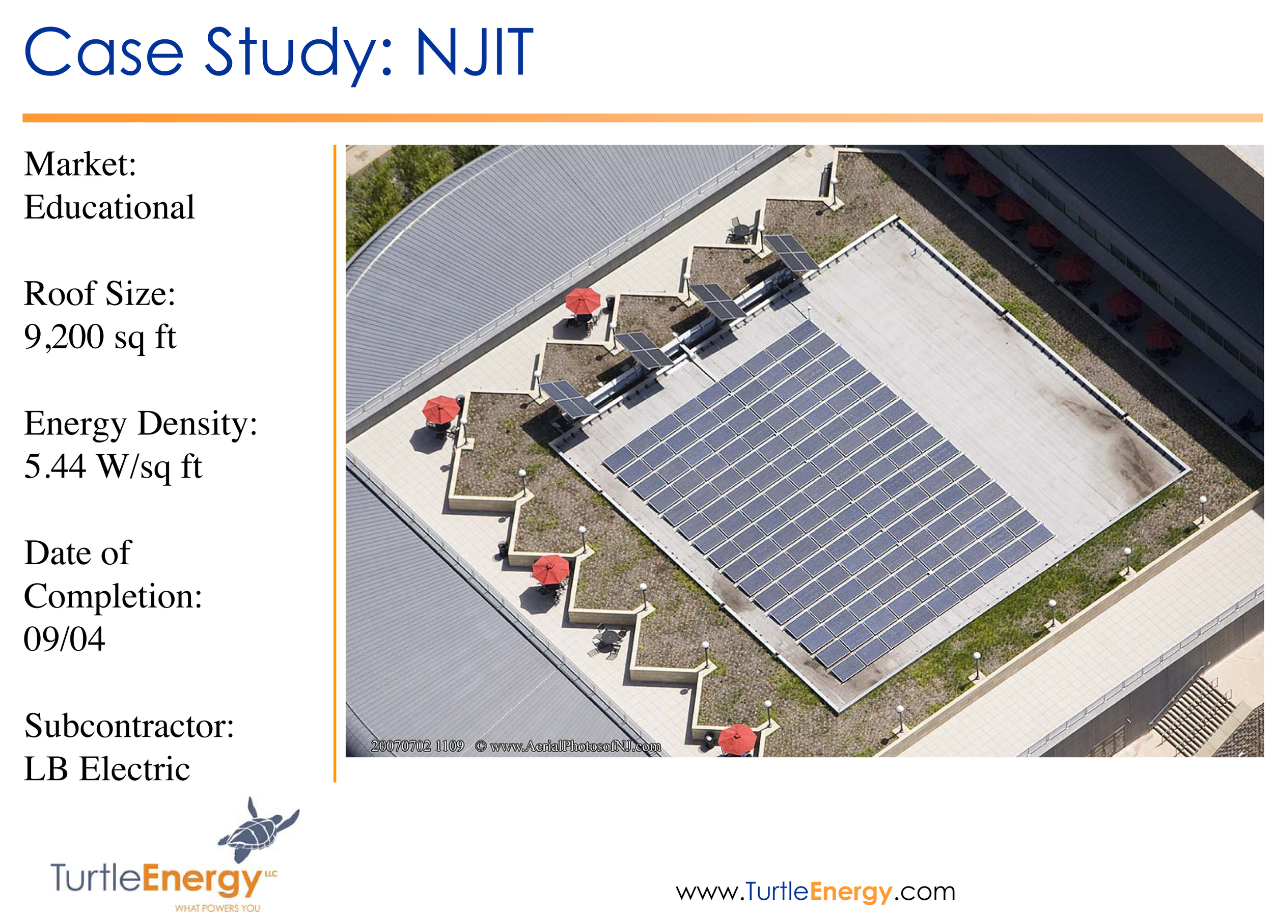
85. Array Area, multiple angles
86. Staging Area, multiple angles
87. Utility Only:
88. Transformers: especially Oil Filled Transformers (do not locate inverters near)
89. Substation
90. Any objects that may interfere with or enhance conduit routes (i.e. catwalks, existing conduit, a wall that must be penetrated)
91. Enclosures: If necessary items have not been enclosed, please list the item, date engineering will receive it, and how it will be transmitted:
COMMISSIONING SCHEDULE
Prior to System Substantial Completion EPC Provider technical personnel, with the assistance of the equipment manufacturer(s) as needed, will perform a complete commissioning of the Generating Facility following the Commissioning procedures outlined in this Attachment as well as other standard tests, inspections, safety and quality checks. All testing and commissioning will be conducted in accordance with the manufacturer’s specifications. Owner reserves the right to have the testing and Commissioning results verified by the Commissioning Engineer.
These Commissioning testing procedures for photovoltaic systems and major components are intended to determine system performance to the specification. The tests are designed to verify that the system, as installed, is safe for personnel as well as equipment, and to establish or verify system operation. The tests shall be used to determine actual post-construction operational, performance, and safety characteristics. [These tests are based in part on the draft IEEE Recommended Practice document (P 1373, June 1997) and focus on utility PV acceptance tests.]
For identification purposes, Owner or its agent, EPC Provider or its agent, and 3rd-party engineer are identified as follows:
1. Project Informatio
2. System Description
Tracking plane, tilted Axis Axis Tilt 3° Axis Azimuth -20°
Rotation Limitations Minimum Phi -45° Maximum Phi 45°
Backtracking strategy Tracker Spacing 4.19 m Collector width 1.68 m
Inactive band Left 0.01 m Right 0.01 m
Horizon Average Height 3.7°
Near Shadings Adjoining Vegetative Buffers
PV Arrays Characteristics (2 kinds of array defined )
PV module Si-mono Model SW 235 mono
Manufacturer SolarWorld
Array#1: Number of PV modules In series 13 modules In parallel 1833 strings
Total number of PV modules Nb. modules 23829 Unit Nom. Power 235 Wp
Array global power Nominal (STC) 5600 kWp At operating cond. 4939 kWp (50°C)
Array operating characteristics (50°C) U mpp 353 V I mpp 13996 A
Array#2: Number of PV modules In series 13 modules In parallel 97 strings
Total number of PV modules Nb. modules 1261 Unit Nom. Power 235 Wp
Array global power Nominal (STC) 296 kWp At operating cond. 261 kWp (50°C)
Array operating characteristics (50°C) U mpp 353 V I mpp 741 A
Total Arrays global power Nominal (STC) 5896 kWp Total 25090 modules
Module area 42068 m²
Array#1 : Inverter Model Sunny Central 500-HE-US
Manufacturer SMA
Characteristics Operating Voltage 300-600 V Unit Nom. Power 500 kW AC
Inverter pack Number of Inverter 10 units Total Power 5000 kW AC
Array#2 : Inverter Model Sunny Central 250U
Manufacturer SMA
Characteristics Operating Voltage 300-600 V Unit Nom. Power 250 kW AC
1. Normal Operating Model
Main system parameters System type Grid-Connected
Horizon Average Height 3.7°
PV Field Orientation tracking, tilted axis, Axis Tilt 3° Axis Azimuth -20°
PV modules Model SW 235 mono Pnom 235 Wp
PV Array Nb. of modules 25090 Pnom total 5896 kWp
Inverter Model Sunny Central 500-HE-US Pnom 500 kW ac
Inverter Model Sunny Central 250U Pnom 250 kW ac
Inverter pack Nb. of units 11.0 Pnom total 5250 kW ac
User's needs Ext. defined as file Workbook14.csv global 9547 MWh/year
Horizon Average Height 3.7° Diffuse Factor 1.00
Albedo Factor 100 % Albedo Fraction 0.85
Height [°] Azimuth [°]
5.0 -120
3.0 -40
3.0 40
5.0 120
PV Array loss factors
Thermal Loss factor Uc (const) 23.2 W/m²K Uv (wind) 4.5 W/m²K / m/s
=> Nominal Oper. Coll. Temp. (G=800 W/m², Tamb=20°C, Wind velocity = 1m/s.) NOCT 46 °C
Wiring Ohmic Loss Array#1 0.43 mOhm Loss Fraction 1.5 % at STC
Array#2 8.2 mOhm Loss Fraction 1.5 % at STC
Global Loss Fraction 1.5 % at STC
Array Soiling Losses Loss Fraction 3.0 %
Module Quality Loss Loss Fraction 1.5 %
Module Mismatch Losses Loss Fraction 2.0 % at MPP
Incidence effect, ASHRAE parametrization IAM = 1 - bo (1/cos i - 1) bo Parameter 0.05
System loss factors
AC wire loss after inverter Wires 1 m 2x1200 mm² Loss Fraction 1.6 % at STC
External transformer Iron loss 5817 W Loss Fraction 0.1 % at STC
Resistive/Inductive losses 0.1 mOhm Loss Fraction 1.0 % at STC
2. BILL OF MATERIALS
3. System Specifications
Module STC Rating
240W &250W
Module PTC Rating TBD
Inverter CEC Efficiency 98%
Overall Array STC (DC kW) ~6000
Overall Array PTC (AC kW) ~5000
Predicted KWh/yr (typical) 8500 MWH
235W SOLAR WORLD W SMA500HE-US + SMA250HE –US
Balances and main results
GlobHor T Amb GlobInc GlobEff EArray E_Grid EffArrR EffSysR
kWh/m² °C kWh/m² kWh/m² kWh kWh % %
Jan 55.1 -1.05 73.8 69.9 394393 381851 12.70 12.29
Feb 63.5 0.57 81.0 77.3 433496 419504 12.72 12.31
Mar 113.4 6.84 144.3 138.9 753308 728240 12.41 12.00
Apr 149.4 12.85 184.9 179.1 932859 901521 11.99 11.59
May 184.9 15.53 221.1 214.2 1100382 1062997 11.83 11.43
June 182.6 21.77 212.6 205.7 1017923 984941 11.38 11.01
July 195.8 25.27 231.2 224.3 1090516 1055039 11.21 10.85
Aug 153.0 24.97 181.2 175.1 845851 818980 11.10 10.75
Sep 110.5 18.72 133.2 128.1 647456 627169 11.55 11.19
Oct 112.0 13.45 150.6 145.0 754369 731104 11.91 11.54
Nov 64.2 8.91 87.9 83.6 448333 434562 12.13 11.76
Dec 49.6 2.28 70.0 66.4 365911 354876 12.42 12.04
Year 1434.2 12.57 1771.8 1707.7 8784798 8500783 11.79 11.41
Legends:
GlobHor: Horizontal global irradiation
T Amb: Ambient Temperature
GlobInc: Global incident in coll. plane
GlobEff: Effective Global, corr. for IAM and shadings
EArray: Effective energy at the output of the array
E_Grid: Energy injected into grid
EffArrR: Effic. Eout array / rough area
EffSysR: Effic. Eout system / rough area
DAS Commissioning
1. DAS wiring
Verify that there are no loose or damaged data wires. Verify that DAS wiring is tight and neat.
2. Meteorological station
Verify that meteorological station is sited in a location within the Generating Facility footprint that is representative of the entire Generating Facility, and is free of shading or obstruction. Verify that that the meteorological station is mounted properly and secure. Verify that the meteorological station junction box wiring is tight and neat. Verify that the meteorological station is operating properly and calibrated.
3.2.1 Insolation Sensor
Verify that there is an insolation sensor for each plane of array applicable to the Generating Facility, as well as one sensor fixed in a horizontal plane. Verify that all insolation sensors are properly adhered, cleaned, and calibrated.
3.2.2 Anemometer
Verify that anemometer is calibrated, properly installed, and functioning properly.
3.2.3 Temperature Probes
Verify that there is a temperature probe measuring both the ambient temperature and the cell temperature, and that both probes are functioning.
3. DAS Communication
Verify that cell or DSL modem is functioning properly.
4. Battery back-up
Verify battery back-up is operating
5. Time / Date
Verify that time / date is properly set.
6. Data Logger
Verify that data, from each sensor, is being logged and saved.
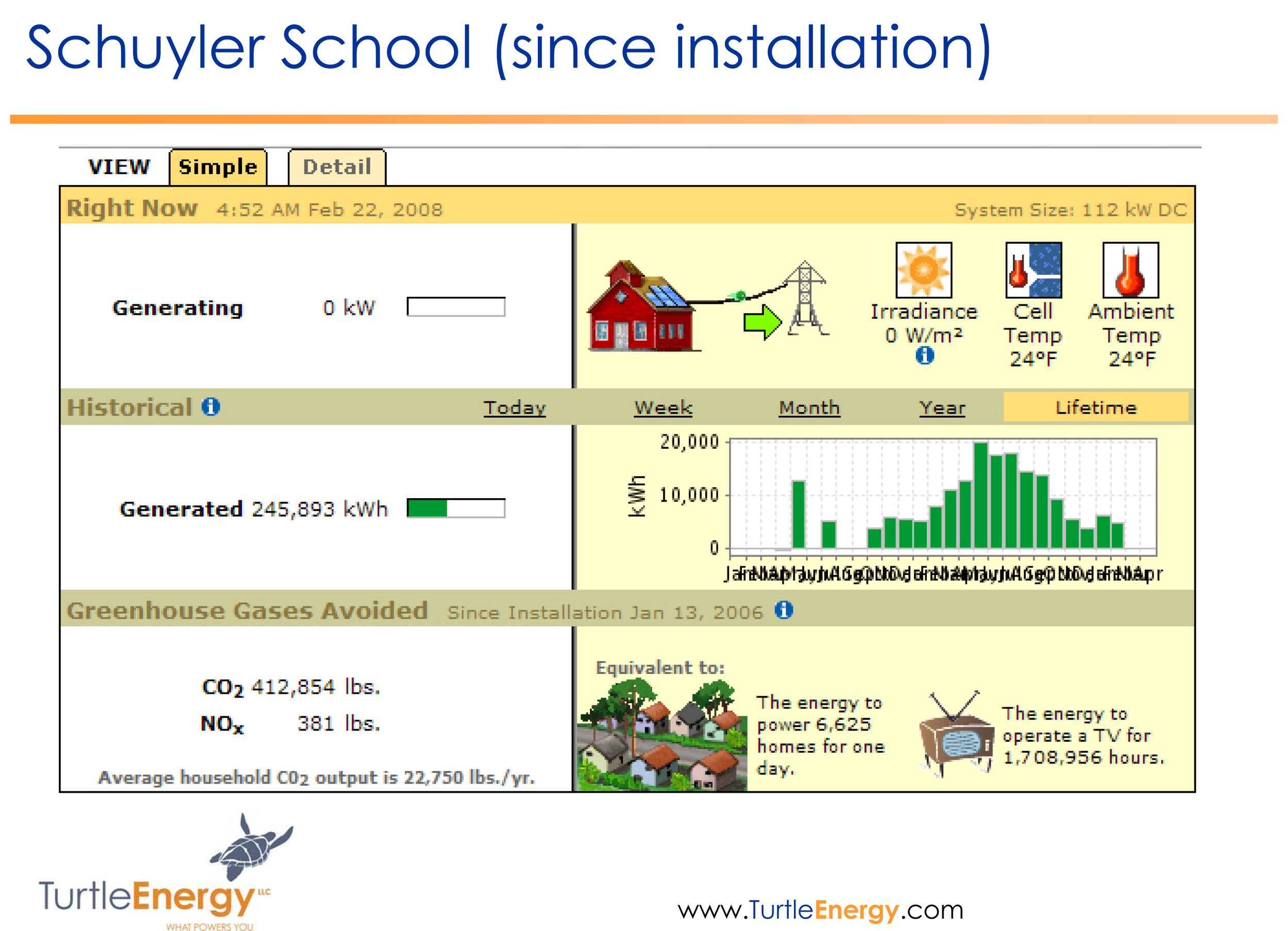
7. On-Site Meter Display
Verify that meter display is outputting data - including kW, kWmax, and kWh (total).
8. Power Metering
Verify that meter is mounted, calibrated, and is working properly. Verify that pulser assembly is calibrated and functioning (if applicable).
9. Verify data read.
Supply 3 days of data verified with a meter read.
4. Visual and Mechanical Commissioning
1. Visual Inspections – General
Make sure all disconnect switches are open and power is not applied.
4.1.1 PV Modules and Module Wiring
Verify that all connectors are properly mated, module cables are properly secured to module frame, no debris on module surface, no physical damage to module frames or laminates, and ground wire and lug are securely attached to module frame.
4.1.2 Source Circuit (Combiner) Junction Boxes
Verify that all connectors are secured, field wiring terminations are tight, field wiring is properly polarity-marked with colored tape or jacket color, ground wire is securely attached, labels are in place, and all covers are secured.
4.1.3 DC and AC Disconnect Switches
Verify field wiring terminations are tight, field wiring is properly polarity-marked with colored tape or jacket color, conduit connections are tight and bushings uses (if applicable), ground wire is securely attached, and all covers are secured.
4.1.4 Inverter(s)
Verify field wiring is routed properly, field wiring terminations are tight, field wiring is properly polarity-marked with color tape or jacket color, conduit connections are tight and bushings used (if applicable), ground wire is securely attached to inverter, labels are in place, and all covers are secured.
4.1.5 Alignment of Structural Components
Visually check that the rows of modules have been installed in straight lines that are parallel to each other. Check that the rows are level, and do not contain excess waviness.. Verify field wiring is routed properly, field wiring terminations are tight, field wiring is properly polarity-marked with color tape or jacket color, conduit connections are tight and bushings used (if applicable), ground wire is securely attached to inverter, labels are in place, and all covers are secured.
2. Visual Inspections – Tracking System [if applicable]
4.2.2 Torque tube bearing caps
Ascertain that each torque tube bearing cap ([ ] caps per torque tube) has been installed correctly.
4.2.3 Bolts and Retaining Nuts
Check all of the anchor-bolts and nuts for proper installation and check for tightness of nuts on the bolts. (Typically [ ] per array structure.)
4.2.4 Motors
4.2.5 LINKAGES
Visually check that the linkages are properly installed.
Slew Rings/ Gear Drives are properly greased & sealed.
Hydraulic lines should be fastened to the support structure at regular intervals.
4.2.6 Installation of Dampers, check for proper tension/ compression in dampers to preventive harmonic movement of the trackers.
4.2.7 Alignment of Structural Components
Visually check that the rows of modules have been installed in straight lines that are parallel to each other. Check that the rows are level, and do not contain excess waviness due to torque tube loading. Verify field wiring is routed properly, field wiring terminations are tight, field wiring is properly polarity-marked with color tape or jacket color, conduit connections are tight and bushings used (if applicable), ground wire is securely attached to inverter, labels are in place, and all covers are secured.
4.2.8 Tracking. (This part of the inspection is accomplished over an entire day.)
Observe each array structure during the morning, mid-day, and afternoon.
The tilt of the modules on the torque tubes should be the same on each row.
When the sun is at it’s zenith, the modules should be level.
Note: The torque tubes rotate in unlubricated Teflon bearings. Some snapping, popping, or cracking noises are normal during movement of the torque tubes.
4.2.9 During installation of the trackers, preventative action for known failure modes must be taken by the installer. These failure modes and their respective preventative actions are listed below:
5. Electrical Commissioning
Electrical Check-Out
Make sure all disconnect switches are open and power is not applied.
5.1.1 Resistance to Ground
Measure hardware components metal frames and housing resistance to ground.
1. Array Structure
2. Junction Box
3. DC Disconnect Frames
4. Inverter Frame
5. AC Distribution Panel
6. Other
5.1.2 Disconnect Switches
Make sure all disconnect switches are open, fuses are removed from combiner boxes, and that power is not applied.
5.1.3 Source Circuit Voltage Polarity Tests
Measure and record in section #####, each source circuit’s open circuit voltage and note the amplitude and polarity. Each string must be within three percent of the mean. Current Measurement are made later after all source circuit polarity has been verified. Complete this section for each inverter first before moving to starting the inverter system.
5.1.5 Combiner Box Fuse
Insert Comber Box fuses
5.1.6 DC Disconnect Switches
Verify the polarity and open-circuit DC voltage magnitude of PV input to switch are correct for each disconnect switch.
5.1.7 Activate DC Disconnect Switches
Turn on DC Disconnects (not the inverter’s DC interface).
5.1.8 Inverter DC Input
Verify polarity and DC voltage magnitude at the DC Interface are correct.
5.1.9 Inverter AC Input
Verify polarity and AC voltage magnitude of utility connection to inverter are correct.
2. System Operational Tests
5.2.1 Apply AC power to the inverter (close the circuit breaker and/or AC disconnect switch).
5.2.2 Apply DC power to the inverter (close DC disconnect switch)
3. System Operation
5.3.1 With the system operating verify that system AC output ceases when the DC disconnect switch is shut off.
5.3.2 With the system operating verify that the system AC output ceases when the AC disconnect switch is shut off.
1. System Data
5.4.1 Commissioning Tests – Before Substantial Completion
Open Circuit Voltage, Inverter, and String I-V Curve Trace tests shall be performed in accordance with procedures detailed in this section 5.5.1, and test data shall be recorded in Section 5.5.3, prior to commissioning of the Generating Facility.
Pre-Substantial Completion Commissioning Test Procedures:
5.4.1.1 Open Circuit Voltage Test
Purpose: Open Circuit Voltage Testing provides a simple method to determine that all strings are properly connected (module and string polarity) and that all PV modules are producing an appropriate voltage level.
Scope: All Strings
Party: EPC Provider technical personnel
Schedule: During Commissioning
Equipment/Materials:
1. rubber insulating gloves
2. voltmeter with an accuracy of at least 1 percent of reading
3. fuse puller
4. infrared thermometer or thermocouple
5. PV specification for Voc as a function of temperature
6. jumper wire
Conditions:
This test will be conducted under full sun (>500 W m 2) and stable sky conditions, generally between the hours of 10:00 a.m. and 2:00 p.m. If such conditions are not available due to the season of the year, then the EPC Provider shall not conduct such test until the earlier of the date on which such conditions exist and 3 business days following the date on which the test would otherwise have been conducted. If, upon the expiration of the foregoing period, such conditions are still not available, then the test will be conducted under stable sky conditions with a minimum irradiance of 200 W/m2; provided, however, that Owner shall have the option to cause the EPC Provider to conduct any such test on the original date therefor regardless of the sky conditions on such date.
Procedure:
7. Measure the temperature of the PV modules using an infrared thermometer or thermocouple. (It is sufficient to measure the temperature of 2-3 modules and take the average).
8. Calculate Expected Voc: Referring to the PV manufacturer supplied equation for Voc as a function of temperature, calculate the expected Voc of each string.
9. Remove Fuses: Wearing rubber insulating gloves and using a fuse puller, carefully remove the fuses from the combiner box. Failure to remove the fuses will result in identical voltage measurements for every string since they are in parallel with the fuses in place.
10. Test String Voltages: Place the positive lead on the fuse block of the string you are testing while the negative lead is attached to the negative block. Continue testing each string by moving to each positive string fuse block. Test and record the voltage of each electrical string.
Criteria:
11. For stable sky conditions and irradiance above 500 W-m-2, string voltages should conform to within 5% of expected voltage as calculated in Step 2 above and each string should conform to within 2% of the average string voltage in the same combiner box under identical temperature and irradiance conditions.
12. For irradiance less than 500 W m 2or for unstable sky conditions (if irradiance changes by more than 10%, or ambient temperature changes by more than 5°C), compare each string’s measured voltage to periodic measurements on a known good (reference) string. The reference string must be measured at irradiance above 500 W m 2 and its measured voltage must be within 5% of the voltage calculated using Step 2 above. Voltage on non-reference strings should be within 5% of the reference string voltage under the same temperature and irradiance conditions.
13. For irradiance less than 200 W m 2, test results may be used only to confirm proper string connection, and not to evaluate voltage performance.
5.4.1.2 Inverter Commissioning
Purpose: Verify the proper operation of the inverter systems
Scope: All inverters
Party: EPC Provider and/or manufacturer, with EPC Provider supervision
Schedule: At inverter start-up
Equipment/Materials:
14. rubber insulating gloves
15. digital multi-meter an accuracy of at least 1 percent of reading for voltage
16. other equipment as required by manufacturer
Procedure: Follow all manufacturer’s guidelines for inverter start-up and commissioning, including verification of safety and control features.
Conditions: No special conditions apply.
Criteria: The inverter and controls should operate as stated in the purchaser or manufacturer specifications.
Comments: Remote functions should only be tested on those systems that will utilize this feature.
5.4.1.3 String I-V Curve Test
Purpose: I-V curves are useful for identifying array problems and characterizing array performance. The purpose of this test is to compare strings on a qualitative basis. For this test, I-V Curve Traces will be taken on a sample size consisting of all strings in 10% of all combiner boxes . I-V Curve Traces quantify actual photovoltaic module or string characteristics.
Scope: A sample size consisting of a sample of all strings in 10% of all combiner boxes.
Party: EPC Provider technical personnel
Schedule: During Commissioning
Equipment/ Materials:
17. rubber insulating gloves
18. I-V Curve Tracer or similar instrument
Procedure:
19. Follow the manufacturer’s procedures for use of the I-V curve tracer.
20. Isolate the portion of the array of interest (plus and minus leads) from the inverter (a DC disconnect switch may suffice) and from other array segments. Connect the curve tracer load to the array leads (be aware of array and load polarities). Sweep the load such that it operates the array over its range of Voc and Isc (or as the load will allow). Record voltage and current readings for at least 10 steps.
21. Along with the series of current voltage pairs, array and ambient conditions should be recorded for each curve including:
- Irradiance (of the appropriate components and orientation)
- Module Temperature
- Ambient Temperature
- Wind Speed (Optional)
- Date and Time
22. An indication of irradiance stability, such as pre and post curve irradiance, may also be recorded and is especially important if the curve takes more than one second.
23. The measurement equipment must be capable of monitoring the array with sufficient speed and accuracy. During the curve sweep, typically only the array current and voltage are measured, with irradiance stability measurements taken before and after the curve, and the remaining parameters measured once before or after the curve.
Conditions:
24. I-V curves must be taken under clear and stable sky conditions. For this test, irradiance must be above 500 W m 2.
25. A reasonable attempt will be made to perform this test under ideal sky conditions; however, if ideal weather is not anticipated because of seasonal changes, the test will not be required for acceptance.
Criteria:
The string Voc should meet the criteria defined in Section 1 – Open Circuit Voltage Test above. The string Isc should meet the criteria defined below:
26. Under sky conditions of 500 W/m2 or greater, the measured current should be within 5% of the expected Isc calculated using equation below:
Where:
27. n = number of modules in parallel in test segment
28. Isc, expected = expected short-circuit current of the test segment, A
29. Isc, REF = module short-circuit current at some specified reference conditions, A
30. G = measured plane of array irradiance, W-m-2
31. GREF = irradiance at some specified reference conditions, W-m-2
32. 0.95 = factor to account for soiling, misalignment, and other factors.
33. Under sky conditions of less than 500 W/m2, the measured short circuit current should be within 10% of the Isc calculated using the above equation.
All I-V curves should be similar in shape (other than differences due to changes in irradiance or temperature).
This test will be conducted under full sun (>500 W-m-2), generally between the hours of 10:00 a.m. and 2:00 p.m. If such conditions are not available due to the season of the year, then the EPC Provider shall not conduct such test until the earlier of the date on which such conditions exist and 3 business days following the date on which the test would otherwise have been conducted. If, upon the expiration of the foregoing period, such conditions are still not available, then the test will be conducted under stable sky conditions with a minimum irradiance of 200 W/m2; provided, however, that Owner shall have the option to cause the EPC Provider to conduct any such test on the original date therefore regardless of the sky conditions on such date.
Comments: If results show anomalies, including fill factor, voltages, or currents outside expected limits or humps on the curve, then investigate for bypass diode conduction, out-of-tolerance module performance, or other possible problems. Rectify any flaws and re-test.
5.4.2 Operating Verification Tests – After Substantial Completion, Before Final Completion
Operating Current and Operating Voltage tests shall be performed in accordance with procedures detailed in this section 5.5.2, and test data shall be recorded in Section 5.5.3, prior to Final Completion of the Generating Facility.
5.4.2.1 Operating Current and Operating Voltage Test
Purpose: The purpose of this test is to ensure that all strings are producing an adequate and consistent operating current and voltage.
Scope: All strings, after connection with utility grid and inverter start-up
Party: EPC Provider technical personnel
Schedule: After Substantial Completion (Commissioning), before Final Completion
Equipment/Materials:
34. rubber insulating gloves
35. DC clamp-on ammeter, 0-40 A scale with 2 per cent. of full scale accuracy
Procedure:
36. Start the Inverter: Start the inverter if it is not already running, making sure all fuses are installed. Wait 5 minutes for the power tracker to stabilize.
37. Prepare for Readings: Open the combiner box, turn on the ammeter, and carefully zero the meter. Keep the clamp away from large bundles of wire, as they will affect the zero, and therefore the actual reading on the meter.
38. Record the “Zero” Value: Wearing rubber insulating gloves, place the meter near a string’s homerun wire. Record the “zero” value.
39. Record the Current Value: While still wearing gloves, clamp the meter on each service loop in the box, recording the current readings.
40. Calculate Actual Current: Calculate and record the actual string currents as the difference between the string current reading and the “zero” value.
Example:
“Zero” value = 0.3 A
Current reading = 3.0 A
Actual Current: 3.0 A - 0.3 A = 2.7 A
41. Record the Current Voltage Value: While still wearing gloves, measure the voltage across a closed breaker
Conditions: Measurements will be made during clear and stable sky conditions. The total inverter output should be at least 50% of the aggregate rating of the active inverters. This test will be conducted under full sun (>500 W-m-2), generally between the hours of 10:00 a.m. and 2:00 p.m. If such conditions are not available due to the season of the year, then the EPC Provider shall not conduct such test until the earlier of the date on which such conditions exist and 3 business days following the date on which the test would otherwise have been conducted. If, upon the expiration of the foregoing period, such conditions are still not available, then the test will be conducted under stable sky conditions with a minimum irradiance of 200 W/m2; provided, however, that Owner shall have the option to cause the EPC Provider to conduct any such test on the original date therefore regardless of the sky conditions on such date.
Criteria: Under clear and stable sky conditions with irradiance greater than 500 W m 2, current readings within each combiner box should be within 5% of the average under identical sky conditions. A reasonable effort shall be made to conduct this test under conditions with irradiance greater than 500 W m 2, however, if such conditions are not available in the commissioning period, then the Current Test will be performed as a sign-of-life test only, without the 5% criteria.
5.4.2.2 System Output Verification
Purpose: Verify the kWh output of the Generating Facility to system design
Scope: the Generating Facility
Party: EPC Provider, with Owner and/or 3rd-party engineer supervision
Schedule: After Commissioning, before Final Completion
Equipment/Materials:
42. functioning DAS with pyranometer measuring irradiance in the plane of the array(s) of the Generating Facility providing 15-minute interval data.
Procedure: Record DAS system for 5 continuous, uninterrupted days and compare actual system output to expected output per system design under recorded insolation for same time period.
Conditions: No special conditions apply.